What Are You Looking For?
What Are You Looking For?

⚡ High breaking capacity, withstands up to 500kA
⚡ Excellent dynamic thermal stability
⚡ Optimized heat dissipation with natural air duct design
⚡ Standardized structural parts for high efficiency
⚡ Use of reliable, well-known brand electrical components
⚡ Enhanced safety and technological advancement
Item NO. :
GGDCertificate :
CQCLead time :
35 DaysPayment :
T/TMOQ :
≥1Warranty :
1 YearLow voltage Fixed Switchgear GGD
Enecell is Low voltage Fixed Complete Switchgear Company, Control Equipment Switchgear Manufacturer, GGD low voltage switchgear (fixed switchgear) is suitable for power users such as power plants, substations, industrial and mining enterprises, and is used for power conversion, distribution and control of power, lighting and distribution in the power distribution system. This product has high breaking capacity, good dynamic thermal stability, flexible electrical solutions, convenient combination and strong practicality.
GGD low voltage fixed switchgear (hereinafter referred to as distribution cabinet) is suitable for power users such as power plants, substations, industrial and mining enterprises as AC 50Hz (60Hz), rated working voltage 380V (400V), (690V), rated current up to 6300A distribution system for power, lighting and distribution of electric energy conversion, distribution and control.
GGD has high breaking capacity, good dynamic thermal stability, and a rated short-time withstand current of 50kA. It has the characteristics of flexible electrical scheme, convenient combination, strong practicality, novel structure, and high protection level.
Product Overview
LGGD low-voltage fixed complete equipment is suitable for power supply systems with AC 50-60Hz, rated working voltage up to 660V, and rated current of 6300A and below. It is widely used in low-voltage distribution systems in power plants, substations, industrial and mining enterprises, high-rise buildings, etc., as power receiving, feeding, reactive power compensation, power metering, lighting and motor control center, etc., for power conversion, distribution and control. The product is based on the design principles of safety, economy, rationality and reliability, and has the characteristics of high breaking capacity, good dynamic thermal stability, flexible electrical scheme, convenient combination, strong series and practicality, and novel structure.
This product complies with relevant standards such as IEC60439-1 and GB7251.1 "Low-voltage complete switchgear and control equipment".
Product Model Meaning

Normal Use Environment Conditions
Normal use environment conditions
1. The ambient air temperature is not higher than +40℃, not lower than -5℃, and the average temperature within 24 hours is not higher than +35℃. The equipment should be used at reduced capacity when it exceeds the above environment.
2. The relative humidity does not exceed 50% when the maximum temperature is +40℃. A higher relative humidity is allowed at a lower temperature, such as 90% at +20℃. The impact of condensation that may occur accidentally due to temperature changes should be considered.
3. The installation site is usually installed at an altitude of no more than 2000m. For places above 2000m, the capacity should be reduced accordingly.
4. Install in a place without fire, explosion hazard, severe dust, chemical corrosion, severe vibration and impact.
5. If the above conditions cannot be met, the user and the manufacturer should negotiate to resolve.
Main technical parameters
|
Serial number |
project |
parameter |
|
|
1 |
Rated insulation voltage |
660V(1000V)/AC |
|
|
2 |
Rated operating voltage |
380V(660V)/AC |
|
|
3 |
Overvoltage level |
IV |
|
|
4 |
Pollution degree |
3 |
|
|
5 |
Rated frequency |
50(60)Hz |
|
|
6 |
Rated impulse withstand voltage |
8kV |
|
|
7 |
Main bus |
Rated current |
Up to 6300A |
|
Rated short-time withstand current |
Up to 100kA |
||
|
Rated peak withstand current |
Up to 220kA |
||
|
8 |
Protection level |
IP30 |
|
|
9 |
Equipment height |
2200mm |
|
|
10 |
Device Width |
600,800,1000,1200mm |
|
|
11 |
Equipment Depth |
600,800mm |
|
Note: For the rear wiring solution, a cabinet depth of 1000mm is recommended.
Structural features
The cabinet of this equipment adopts a universal cabinet assembly structure. Because of its flexible and convenient assembly, the parts are designed according to the modularization, the universal coefficient is high, and pre-production can be realized, which not only shortens the production and manufacturing cycle, but also improves production efficiency. The equipment is designed for front and rear operation, rear wiring, and front and rear maintenance of the cabinet.
1. Selection of components in the cabinet
1.1 The equipment has good installation flexibility. The mainstream electrical components at home and abroad can be easily installed in the cabinet. At the same time, according to the principles of economy and rationality, some available old products are retained on the premise of fully considering feasibility.
1.2 Equipped with HD13BX and HS13BX disconnectors, it is easy to operate and labor-saving, and can ensure the safety of maintenance. At the same time, it has full compatibility with the installation of disconnectors (fuse disconnectors) such as QA, QP, QSA, GL, and GLR.
2. Cabinet
2.1 The cabinet frame is usually assembled by partial welding of 8MF cold-bent steel, and can also be assembled by C-profiles. The profiles are equipped with mounting holes with a modulus of 20mm, which are connected by high-strength bolts. It can be assembled into various forms of cabinets without special tools, and has high strength and flexibility.
2.2 The cabinet design fully considers the heat dissipation problem during the operation of the cabinet. There are different numbers of heat dissipation slots at the upper and lower ends of the cabinet. When the electrical components in the cabinet heat up, the heat rises and is discharged through the upper slots, while the cold air is continuously replenished into the cabinet from the lower slots, so that the sealed cabinet forms a natural ventilation duct from bottom to top to achieve the purpose of heat dissipation.
2.3 The cabinet adopts the golden ratio method to design the cabinet shape and the division size of each part in accordance with the requirements of modern industrial product design, so that the whole cabinet is beautiful and generous, and has a new look.
2.4 The cabinet door is connected to the frame with a rotating shaft hinge, which is convenient for installation and disassembly. A mountain-shaped rubber-plastic strip is embedded in the folding edge of the door. When closing the door, the strip between the door and the frame has a certain compression stroke, which can prevent the door from directly colliding with the cabinet body and improve the protection level of the cabinet body.
2.5 The instrument door equipped with electrical components is connected to the frame with multiple strands of soft copper wire. The mounting parts in the cabinet are connected to the frame with knurled screws, so that the whole cabinet forms a complete grounding protection circuit.
2.6 The cabinet surface adopts high-voltage electrostatic spraying technology, which has strong adhesion and good texture. The whole cabinet is matte, which avoids the glare effect and creates a more comfortable visual environment for the on-duty personnel.
2.7 The top cover of the cabinet can be removed when necessary, which is convenient for the assembly and adjustment of the main busbar on site. The four corners of the cabinet top are equipped with lifting rings for lifting and shipping.
2.8 The protection level of the cabinet is IP30, and it can be selected between IP20 and IP40 according to the user's installation site requirements.
3. Busbar system
3.1 The main busbar is installed horizontally on the top of the cabinet. Each phase is composed of a single or multiple rectangular copper bars, supported by a high-strength busbar frame, and has good dynamic stability.
3.2 The cabinet is equipped with a neutral busbar and a main grounding busbar, which are installed under the cabinet. The length of the busbar is determined according to the transportation unit of the equipment. Standard modular mounting holes are provided for the connection of incoming and outgoing cables.
3.3 The busbars are all made of TMY-T2 series hard copper bars. The surface of the copper bar can be tinned, silvered and anti-oxidized as needed to improve the dynamic thermal stability of the busbar and improve the temperature rise of the contact surface.
Ordering Instructions
When ordering, users should provide the following information:
1. Schematic diagram of Feng circuit, primary system diagram.
2. Auxiliary circuit electrical schematic diagram, terminal arrangement diagram. If there is no schematic diagram and terminal arrangement diagram, follow the manufacturer's standards.
3. Equipment layout combination diagram, plane layout diagram.
4. Model, specification, and quantity of main electrical components in the equipment.
5. Inlet and outlet line mode, cable specifications. If busbar connection is required between equipment rooms or incoming line units, data such as busbar span and height from the ground should be provided.
6. Equipment surface color.
7. Other special requirements should be negotiated with the manufacturer.
Warehouse Real Scene

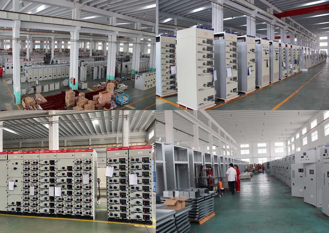
Generate Workshop

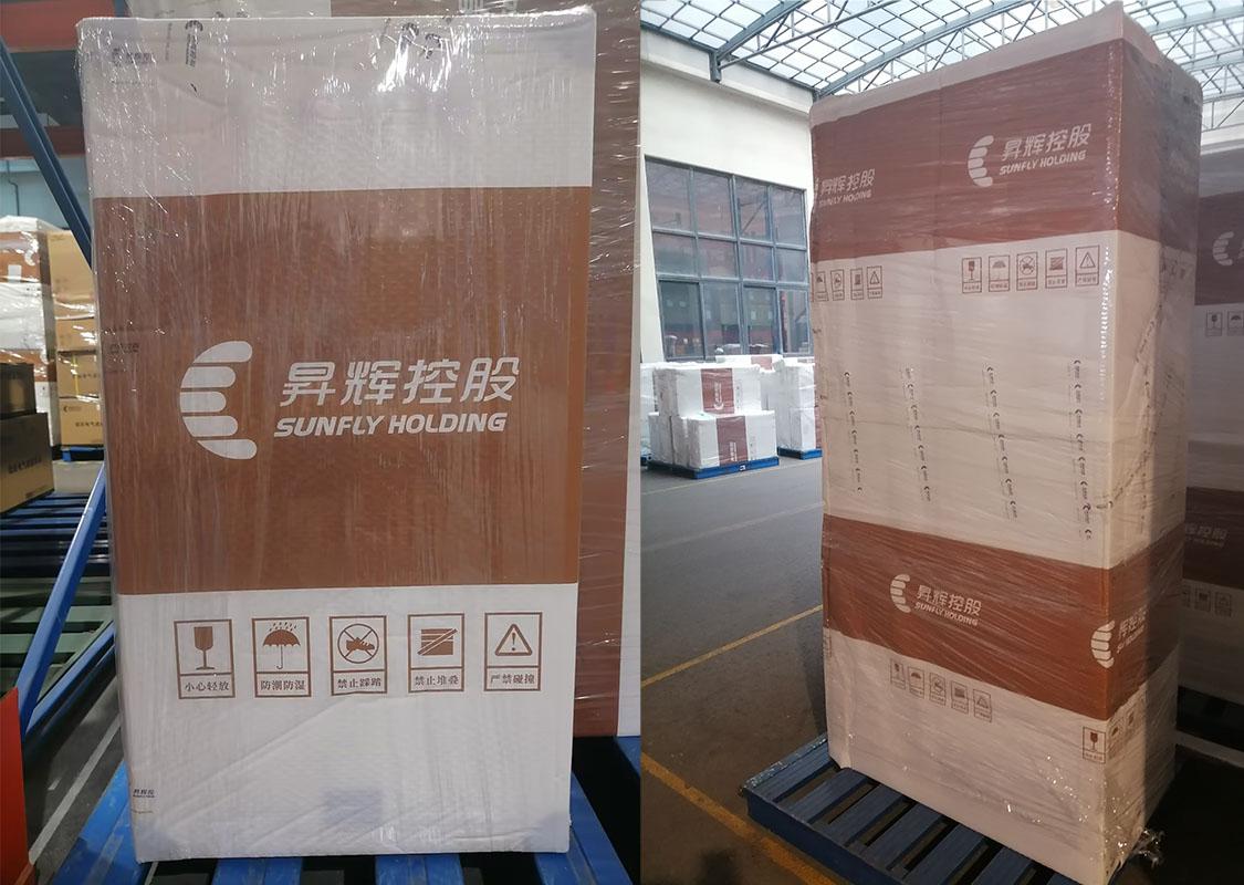
Product Packaging

Hot Tags :

Can't Find Target Products? contact us!